Do You Have A Project We Can Help With?
Kiepe Electronic Speed Monitor JMNC
APPLICATION
The Electronic Speed Monitor relays JMNC is used in connection with a pulse sensor to monitor the rotational speed and standstill of drives.
Pulse sensors according to NAMUR-EN 50227 as well as npn pulse transducers (Kiepe model EOG) can be connected to the speed monitor relay.
The pulse output is fed to the speed monitor relay where the pulse frequency is compared with the frequency set by the control of the relay. When the input frequency passes the set frequency the internal output relay is switched.
Warning or control equipment can be connected to this output relay and operate when the speed either increases or decreases from the set point. The output relay contacts of JMNC are gold plated to improve true contact even in case of low voltage circuit operations.
The operation of the relay can be inhibited during start-up of the monitored drive by adjusting the start-up potentiometer to the time taken for the drive to reach operating speed.
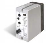
CONSTRUCTION
The control unit JMNC is made of 2 parts. One forms the base and contains a combined edge connector and terminal block, five rubber inserts on three sides for cable entries and two knockout holes in the base are provided for mounting the control unit. The other and main component of the control unit is a printed circuit board which slides into the plastic case and is held in place by a plastic plate which clips into the open side.
The complete plug-in unit is secured to the base by two screws held captive by rubber washers. This arrangement allows withdrawal of the plug-in unit from the base without having to loosen the wiring on the terminal block.
Option
A special design is available to meet requirements where the speed monitor unit should be installed close to the monitored drive and its pulse sensor.
The design consists of speed monitor relay JMNC being installed in a plastic housing, of IP 65 protection, and already wired to a terminal block.
The true operation of the device can readily be observed through the transparent cover of the plastic housing.
The features of this arrangement are:
– Shortened length of screened cable between pulse sensor and relay adjustment at commissioning with visual contact to the drive.
– The output signal of the relay can be interference free transmitted to the control equipment without using the screened cable.
OPERATING PRINCIPLE
The circuit arrangement of the speed monitor relay JMNC makes use of the advantages of digital pulse input. There are no time lags normally encountered with analog devices. The unit compares the time between successive input pulses and its preset frequency.
Differences result in immediate switch-off of the output relay. The output relay will switch, too, if the connected pulse sensor becomes damaged or the power supply fails.
TECHNICAL DATA
Device complies with: EN 50178-94; EN 50081-1; EN 50082-2; EN 60204
Operating Principles: Under speed or standstill
Mechanical: The plug-in base is resistant to tracking and houses the cable entries and connection terminals. The housing contains the plug-in PCB.
Actuating Supply Voltages: AC 230 V, 50 … 60 cyc., other voltages by request.
Voltage Tolerance: ± 10 %
Power Consumption: Approx. 2.5 VA
Power Consumption: Approx. 2.5 VA
Storage Temperature: – 35 °C … + 80 °C
Trip Point Accuracy: < 1 % (at constant temperature)
Reset Differential: 10 % at pre-set speed
Pulse Duration: ≥1.5 ms
Pick-up Time: For the internal output relay of the Speed Monitor unit with starting by-pass it is 150 ms after having connected the JMNC to the actuating supply voltage.
Starting By-pass: 0 – 45 sec. adjust ability
Protection: IP 51 (dust and drip-proof) according to EN 60529
Mounting Position: Vertical
Output Contact: 1 changeover contact
Contact ratings Ie / Ue: AC 2 A / 230 V
OPERATIONS
Monitoring of underspeed or standstill with start-up delay
Adjust the potentiometer to the required start-up delay-time. The internal output relay is energized during the start-up time (contact 8 – 10 closed).
The relay will be cut off if the operating speed is below the trip point (contacts 9 – 10 closed).
Note: In addition, if it is necessary to monitor pulse failure, the Kiepe speed monitor model EDO should be used.
Monitoring of overspeed (maximum speed) without start-up delay
Set the start-up potentiometer to zero (fully left). The internal output relay will be energized (contact 10 – 8, closed) as soon as the operating speed is higher than the adjusted setpoint.
Trusted Partners