Do You Have A Project We Can Help With?
Belt Misalignment Monitoring of Bucket Elevators SBW
APPLICATION
Kiepe Belt Misalignment Switches SBW are used in bucklet elevator installations for monitoring the true tracking of the elevators belt. The switches will operate if the belt exceeds the permissible deviation from the nominal tracking. The switch´s output signal energizes the connected control units to stop the elevator in order to avoid spillage of material, severe damage and serious downtime.
OPERATION
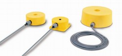
The monitoring of the true tracking of the buckets is realized by mounting a pair of inductive proximity switches near the headpulley on the carrying side and another pair located near the tailpulley on the return side. Misalignment of the buckets becomes detected as soon as a bucket mistracks into the sensing zone of the proximity switch.
The sensing distance of the inductive proximity switches is adjustable by means of a potentiometer accessible from the sensor´s surface. A LED indicates when the sensor´s oscillator field is interfered by a bucket. All switches can be programmed from NO to NC.
TECHNICAL DATA
Device complies with: IEC 947-1; EN 50081-1; EN 50082-2
Mounting: Non-f lush mounting
Operating voltage:
DC-Version: 15 … 60 V
AC-Version: 20 … 250 V
Load current: 400 mA
Surge current: 4 A (AC- type)
Minimum load current: 8 mA (AC- type)
Hysteresis: < 10 % sn
Ambient temperature: – 20 °C … + 70 °C
Protection: IP 67
Switching frequency: AC: 25 Hz, DC: 100 Hz
Connecting cable:
DC: 3 x 0.50 mm2, length: approx. 2 m
AC: 2 x 0.75 mm2, length: approx. 2 m
Output circuit:
DC – PNP – NC / NO – programmable
AC – NC / NO – programmable
OPERATING MODES
Switches in AC-Mode to fit in relay/contactor-circuits.
Up to 4 switches can operate in series when using the NC-mode. The voltage drop of each switch amounts to 6 volts.
Switches in DC-Mode – protected against short- circuits and wrong polarity.
Up to 4 switches can operate as well in series when using the NCmode as in parallel when using the NO-mode. Switches in DC-mode are suitable to fit directly a PLC.
INSTALLATION
The assembly consists of the inductive proximity switches, the connecting cable and a flame resistant mounting plate, together with a gasket, a plastic rear cover and a set of fixing screws.
A hole must be cut in both sides of the chute wall of the bucket elevator. The holes at the headpulley as well as those at the tailpulley should be cut in the travel line of the buckets.
Since the switches are designed for a non-flush mounting a metalfree area should be considered around the switch (please refer to the selection table: min. diam.).
The mounting plates with their gaskets shall be placed on the openings in such a way that they fully cover and seal the holes. The mounting plates are fixed by means of the supplied screws.
For further information please refer to the mounting instructions.
Trusted Partners